

Explore Knowledge Articles
Back
What Does The Blue Wire or Blue Screw Do on Lutron Devices?
In a Lutron multi-location dimmer setup, the blue wire or blue screw terminal is used for digital communication between the master dimmer and companion dimmers. Unlike traditional analog 3-way systems that rely on mechanical switching, Lutron's system uses this wire to transmit signals that allow the companion dimmers to control the lights indirectly by sending commands to the master dimmer. This enables full dimming functionality from multiple locations, with the master dimmer handling all load control and brightness adjustments.
This article explains the key differences in wiring, operation, and functionality between a traditional 3-way dimmer and a Lutron multi-location dimmer.
Before We Begin
Review common wiring terminology below:
3-way – An application where two in-wall controls operate the same light. A 3-way control has 3 screws or wires (not including the ground).
Line side – The wallbox location where power is brought in from the circuit breaker.
Load side – The wallbox location where the switched leg is brought in from the lighting load.
Common – The screw, or wire, on a 3-way control that is connected to the power at the line side, or switched leg at the load side, of the circuit.
Traveler – The wires that connect two wallbox locations together. Typical applications consist of two travelers running between each location.
Traditional 3-way Controls
Example: TGCL-153P dimmer + 3-way mechanical switch or DVCL-153P dimmer + 3-way mechanical switch
Wiring
- Consists of one dimmer switch and one 3-way switch.
- The switches mechanically alternate the path of current to turn the light on or off.
Operation
- Either switch can toggle the light on/off.
- Only the dimmer can control the brightness of the light.
- The switches are mechanically independent. The position of one switch affects the other.
Below is an animation that demonstrates how 3-way switches control the path of electricity to turn a light on or off:
In the animation, power is delivered from the circuit breaker to the line-side switch (on the left side of the animation). Power is then delivered through a traveler wire to the load-side switch (on the right side of the animation). Finally, power is sent from the switch to the light bulb. Notice how toggling a switch alters the flow of electricity.
Lutron Multi-location Controls
Examples: MACL-153M dimmer + MA-R companion or DVRF-6L dimmer + DVRF-AS companion
Wiring
- Uses one master dimmer/switch and one or more companion dimmers/switches.
- Only one master dimmer/switch can be installed in a multi-location application. Two master dimmers/switches can not control the same load.
- One traveler wire is used for communication between devices (as opposed to power switching in a traditional 3-way). The other traveller delivers the power to the load.
Operation
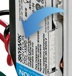
- All companion controls communicate digitally with the master dimmer/switch via the traveler wire connected to the blue screw/wire.
- Lutron companion dimmers can dim the lights from multiple locations.
- Lutron accessory switches can only toggle the lights on/off.
Advantages
- Smooth dimming and advanced features like fade-on/fade-off.
- Cleaner wall experience with matching companion devices.
- Typically supports dimming from multiple locations.
Below is a short animation that demonstrates how the Maestro dimmer and Maestro companions communicate to control a light:
When a user interacts with a Maestro companion device (by tapping the on/off tapswitch or pressing the raise/lower buttons), the companion sends out a digital signal. This signal is sent across the traveler wire that is connected to the blue screw of each Maestro device. Once the master Maestro device receives this signal, it adjusts the light level accordingly.
Frequently Asked Questions
Does a Lutron device with a blue screw or blue wire function when connected to a 3-way switch?
Not every multilocation device supports using a mechanical switch. Refer to your device’s installation instructions or specification sheet to verify.
How does a Lutron device with a blue screw/wire function when connected to a compatible companion device?
Compatible companion devices communicate digitally with their master device via the traveler wire. The same traveler wire must be connected to the blue screw or blue wire of the master and other companion devices. If there is a miswire or an incompatible companion device is installed, the master Lutron device will not function properly.
Was this article helpful?
Thank you! We appreciate your feedback!